Industry Knowledge
Shoulder Diameter Tolerance: The Dimension That Determines Whether a Precision Mold Runs or Fails
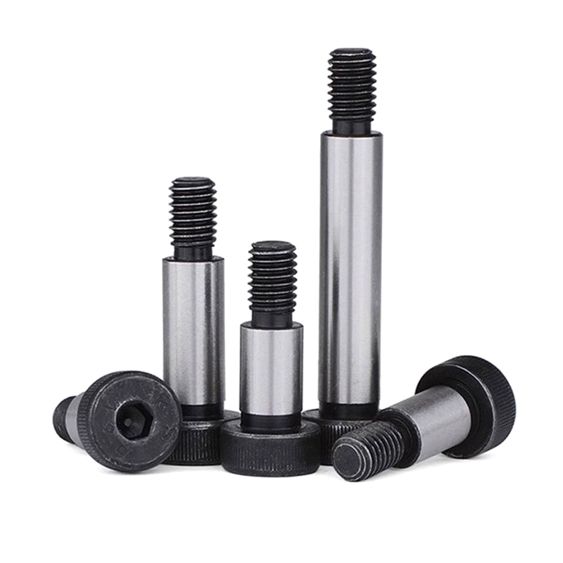
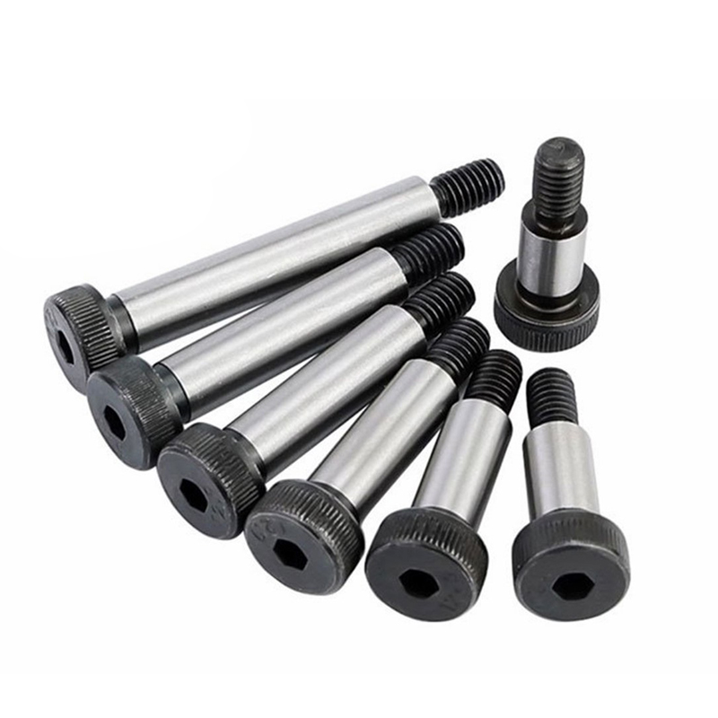
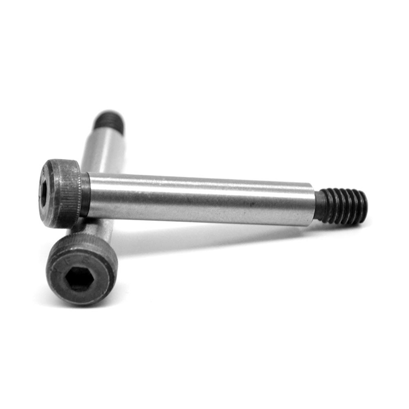
In precision molds and injection molds, the shoulder of a shoulder screw is not merely a structural feature—it is a precision datum. The shoulder diameter tolerance is what governs how accurately a mold component can be positioned and how repeatably it returns to that position across thousands of cycles. Industry practice for high-precision tooling specifies shoulder diameters held to h6 tolerance (negative tolerance only, no oversize), which for a 10 mm shoulder means a diameter range of 9.991–10.000 mm. At this tolerance level, the shoulder fits into a reamed hole with an interference or transition fit that eliminates radial play entirely.
The consequences of inadequate shoulder tolerance are measurable and often expensive. In a stamping die, a limit pin with even 0.02 mm of radial clearance will allow the guided component to shift laterally under the shock load of each press stroke. Over time, this micro-movement enlarges the bore, accelerates wear on both the screw and the die block, and eventually causes dimensional drift in the stamped part. What begins as a tolerance specification problem becomes a production quality problem without any single obvious failure event to diagnose.
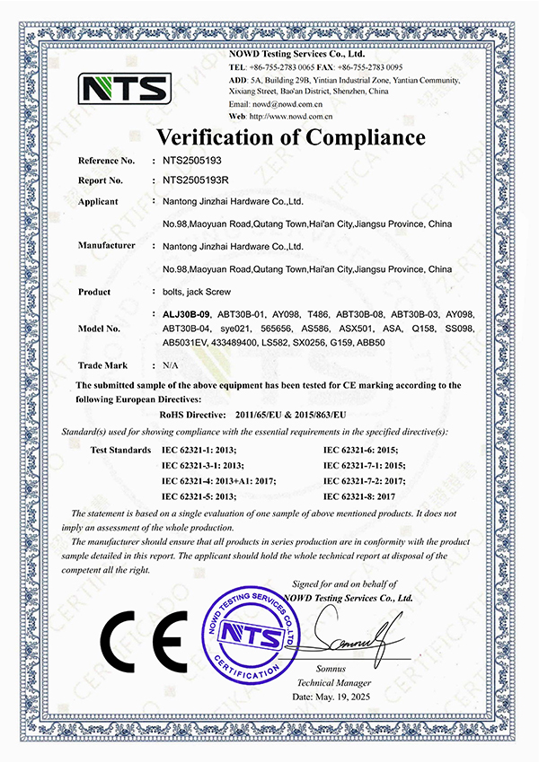
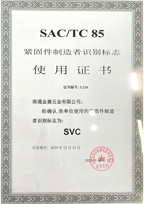
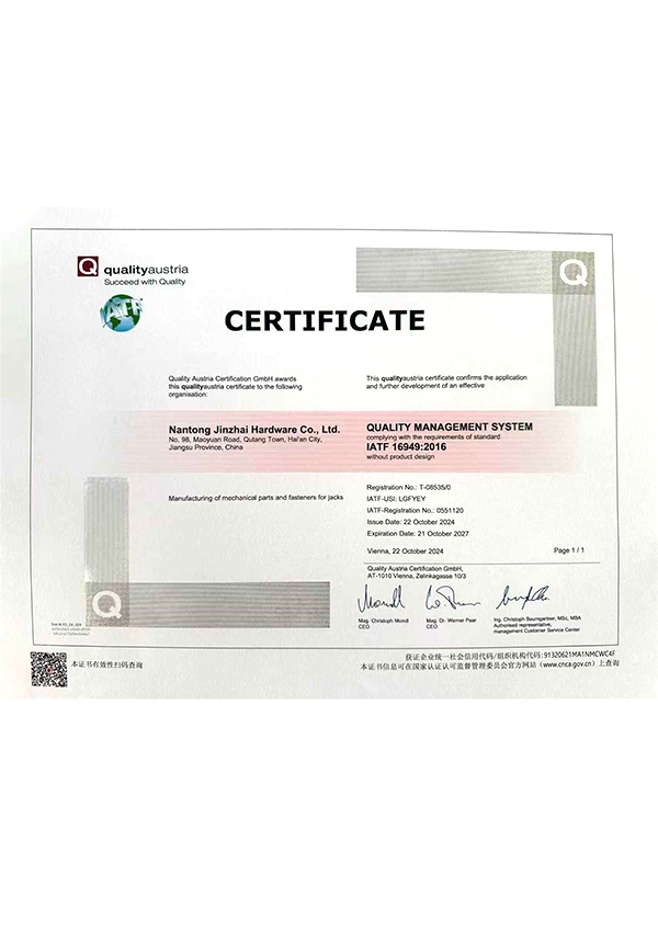
At Shanghai Soverchannel Industrial Co., Ltd., shoulder diameter tolerances for precision tooling applications are held to h6 as standard, with h5 available for customers requiring the tightest possible fit in high-cycle stamping dies and semiconductor tooling. The company's manufacturing plant, Nantong Jinzhai Hardware Co., Ltd., employs cylindrical grinding as the final shoulder finishing operation rather than turning alone, which is what enables sub-micron roundness and diameter consistency across a production lot.
Shoulder Length Precision in Ejector Retainer Applications: Why ±0.05 mm Is Not Good Enough
Shoulder screws used as ejector retainers in injection molds perform a function that is fundamentally different from a fastener holding two plates together. The shoulder length defines the exact stroke limit of the ejector plate—the distance the ejector pins travel forward to push the molded part out of the cavity. If the shoulder length is short by even 0.1 mm, the ejector plate bottoms on the screw head before the ejector pins reach their designed forward position, leaving the part partially unejected. If the shoulder is long by the same amount, the ejector plate overshoots its designed stop position, potentially bending ejector pins or damaging cavity surfaces.
This is why precision injection mold builders specify shoulder length tolerances of ±0.025 mm or tighter for ejector retainer applications—substantially tighter than the ±0.13 mm (approximately ±0.005 inch) tolerance that many standard shoulder screw catalogs publish as their nominal tolerance. The distinction matters when sourcing: a screw that meets catalog tolerance is not necessarily a screw that meets the mold's functional requirement.
Shoulder screws used as ejector retainers also experience a distinctive loading pattern: the shoulder bears a pure compressive axial load at the end of each ejection stroke, transmitted across the annular contact face between the shoulder end and the ejector plate. Surface flatness and perpendicularity of this end face to the shoulder axis therefore directly affect how evenly the load distributes across the retainer pattern. Uneven load sharing across a set of retainer screws is a root cause of ejector plate tipping, which produces inconsistent ejector pin protrusion heights and variable part ejection.
Material and Heat Treatment Choices for Shoulder Screws in High-Load, High-Vibration Environments
Automotive tooling and aerospace component assemblies subject shoulder screws to a combination of radial shear loads, axial tension from the threaded end, and continuous vibration—a stress state that demands a material with both high surface hardness and adequate core toughness. Surface hardness resists wear at the shoulder-bore interface; core toughness prevents brittle fracture under impact loading. Getting the balance wrong in either direction produces premature failure.
| Material |
Typical Surface Hardness |
Core Toughness |
Best Fit Application |
| Alloy Steel (case-hardened, e.g. SCM415) |
58–62 HRC (surface) |
High (soft core) |
Precision molds, stamping dies, automated machinery |
| Through-hardened Alloy Steel (e.g. SCM440) |
38–45 HRC (uniform) |
Moderate |
High-load hydraulic systems, machine tool pivots |
| Stainless Steel 303/304 |
~90 HRB (soft) |
High |
Food processing, pharmaceutical, moderate-load humid environments |
| Stainless Steel 440C (hardened) |
56–60 HRC |
Moderate |
Corrosive environments requiring wear resistance (marine tooling) |
| Custom Ni-Cr-Mo Alloy Steel |
60–64 HRC (surface) |
Very High |
Aerospace components, high-vibration automotive tooling |
As a custom alloy steel fasteners manufacturer, Shanghai Soverchannel Industrial Co., Ltd. engineers Ni-Cr-Mo alloy shoulder screws to application-specific chemistry and case depth specifications. For aerospace and high-vibration automotive tooling, the case depth on a carburized shoulder screw is engineered to a minimum of 0.5 mm—deep enough that the hardened layer is not consumed by the grinding operation that brings the shoulder to final diameter tolerance, while preserving the ductile core that absorbs shock without fracturing.
Imperial vs. Metric Shoulder Screws: Sourcing Realities for Overseas Equipment Assembly and Maintenance
Equipment imported from North America frequently uses imperial-dimensioned shoulder screws—shoulder diameters in fractional inches (3/16", ¼", 5/16", 3/8", ½", and so on) with unified thread forms (UNC or UNF) on the threaded end. When this equipment requires maintenance or tooling replacement in metric-standard manufacturing environments, sourcing the correct replacement shoulder screw becomes a genuine procurement challenge. Substituting the nearest metric equivalent is almost never acceptable: a 6 mm metric shoulder screw has a shoulder diameter of 6.000 mm, while the nearest imperial equivalent (¼") has a shoulder diameter of 6.350 mm—a 0.35 mm difference that eliminates the interference or transition fit the application depends on.
The thread end creates an additional complication. A ¼" imperial shoulder screw typically uses a 10-32 UNF or ¼-20 UNC threaded end, and the tapped holes in the mold or fixture are cut to match. Attempting to use a metric M5 or M6 thread without rethreading the hole is not a viable shortcut—pitch, major diameter, and thread form all differ. For overseas equipment assembly operations that maintain both imperial and metric tooling, maintaining a parallel inventory of imperial shoulder screws is operationally simpler than case-by-case conversion engineering.
Shanghai Soverchannel Industrial Co., Ltd. supplies both metric and imperial shoulder screw series from its manufacturing base at Nantong Jinzhai Hardware Co., Ltd., with full traceability and dimensional certification. For international customers managing mixed-standard equipment fleets, the company can produce imperial shoulder screws to ASME B18.3 dimensional standards in the same production run as metric equivalents, simplifying procurement consolidation without requiring separate supplier relationships.
Shoulder Screws as Pivot Pins in Automated Machinery: Bearing Load Calculation and Wear Life Estimation
In automated machinery and machine tools, shoulder screws functioning as pivot pins for linkages, cam followers, or swinging arms are subjected to radial bearing loads across the shoulder length. Unlike a plain journal bearing where load is distributed across a long contact zone, a shoulder screw pivot concentrates the radial load across the usable shoulder length—typically between one and three times the shoulder diameter depending on the application geometry. Calculating the bearing pressure at the shoulder surface is the first step in predicting wear life.
The projected area bearing pressure formula applies: P = F / (d × L), where F is the radial load in Newtons, d is the shoulder diameter in mm, and L is the effective bearing length in mm. For a case-hardened alloy steel shoulder screw running against a steel bushing or hardened bore, the allowable bearing pressure is typically 100–150 MPa for continuous rotation and 200–350 MPa for oscillating or indexing motion. Exceeding these limits accelerates surface fatigue, produces fretting wear debris, and gradually enlarges the bore—the same failure progression seen in inadequate-tolerance applications but driven by load rather than dimensional error.
Textile equipment and hydraulic system pivot applications add a lubrication consideration that is often overlooked during design. A shoulder screw pivot running dry in a high-cycle textile machine may see surface temperatures exceeding 150°C at the contact zone during sustained production runs, which degrades any oil film and accelerates adhesive wear. Design provisions for lubrication access—a radial grease hole through the bore wall or a circumferential groove in the shoulder—can extend wear life by an order of magnitude in these applications, and specifying a shoulder screw with a surface treatment compatible with the lubricant chemistry is a basic engineering requirement that should be confirmed at the design stage rather than after field failures.
Non-Standard Shoulder Geometries in Aerospace and Automotive Tooling: Beyond the Catalog
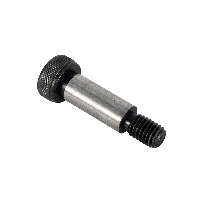
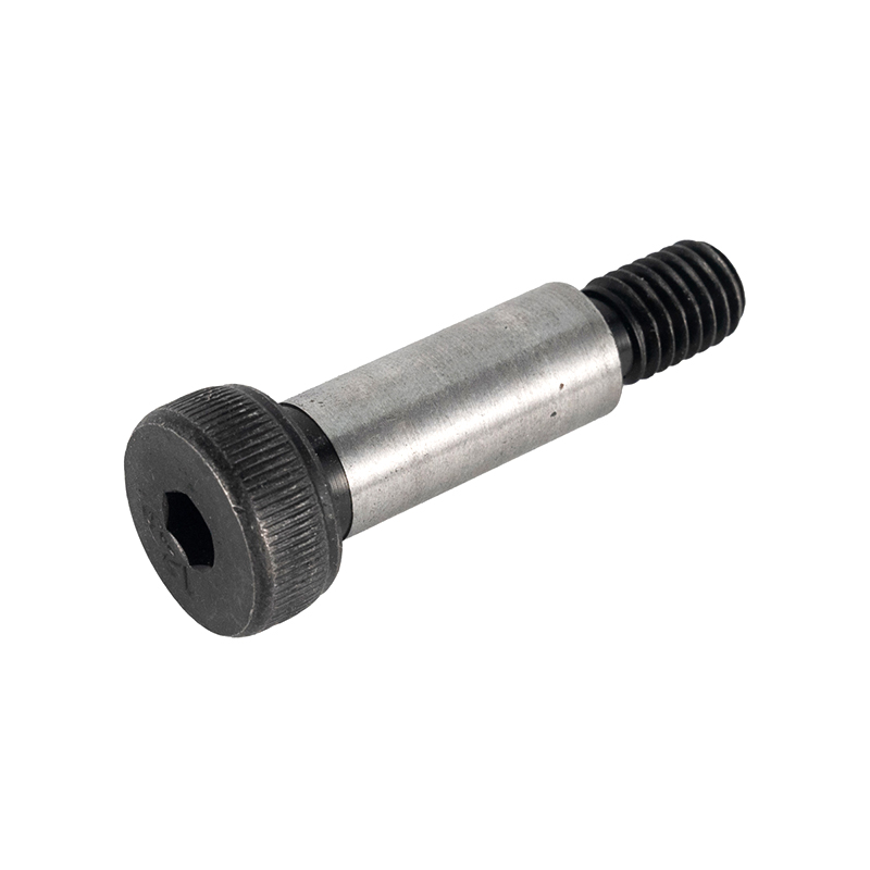
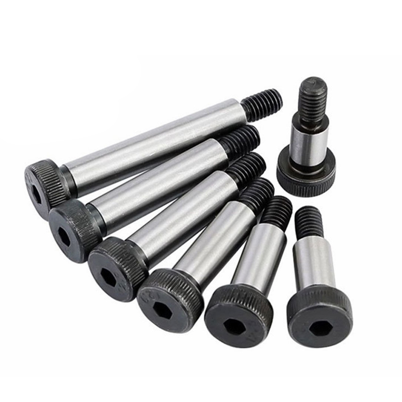
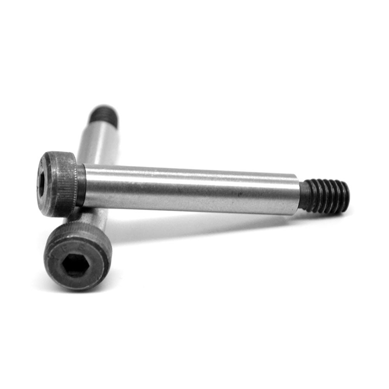
Standard shoulder screws follow a straightforward geometry: cylindrical shoulder, flat underhead bearing face, and a threaded end with a smaller diameter than the shoulder. Aerospace components and specialized automotive tooling frequently demand configurations that cannot be sourced from any standard catalog—and attempting to modify a standard screw in the field (turning down a shoulder, adding a cross-hole, machining a reduced section) almost always compromises the heat treatment and dimensional integrity of the part.
Common non-standard shoulder screw configurations that arise in high-precision tooling include:
- Double-shoulder screws: Two cylindrical shoulders of different diameters on the same shank, used to locate and retain components at two different depth planes simultaneously in complex mold assemblies.
- Relieved-shoulder screws: A reduced-diameter waist section between the shoulder and the threaded end, acting as a controlled elastic element that absorbs shock loading without transmitting it into the thread engagement zone—particularly valuable in high-impact stamping die applications.
- Shoulder screws with cross-holes or axial passages: Used in hydraulic systems and pneumatic tooling where the screw simultaneously serves as a pivot pin and a fluid passage, eliminating a separate port fitting and reducing assembly complexity.
- Flanged shoulder screws: An enlarged flange below the head distributes the axial clamping load over a wider area, preventing embedment into soft material (aluminum or composite) tooling plates without requiring a separate washer component.
- Extra-long shoulder screws with multiple thread pitches: Required in deep mold assemblies where the thread end must engage a plate far below the shoulder bearing zone, with overall lengths extending well beyond standard catalog maximums.
Shanghai Soverchannel Industrial Co., Ltd. is structured specifically to handle this segment of the market. As a manufacturer integrating R&D, production, and sales, the company reviews customer drawings, advises on geometry and material selection, produces prototypes for dimensional and functional validation, and transitions directly into production—all within a single supply relationship that eliminates the engineering-to-procurement hand-off delay common when working with distributors who source from third-party factories.
Surface Treatment Selection for Shoulder Screws: Balancing Dimensional Integrity Against Corrosion Protection
The surface treatment applied to a shoulder screw presents a fundamental tension that does not exist for ordinary fasteners: any coating that adds thickness to the shoulder surface directly subtracts from the dimensional tolerance budget. A zinc electroplating layer of 8–12 µm per side adds 16–24 µm to the shoulder diameter—enough to convert an h6 tolerance shoulder into an oversize part that will not enter its reamed bore without interference. This is why surface treatment selection for precision shoulder screws requires explicit attention to coating thickness, not just corrosion performance.
- Black oxide: The preferred treatment for precision mold and die applications. Conversion coating depth is measured in nanometers rather than microns—effectively zero dimensional impact. Provides mild corrosion resistance sufficient for indoor tooling environments when combined with an oil seal. Compatible with all standard tolerance classes without post-treatment grinding.
- Electroless nickel plating: Deposits a highly uniform layer (typically 12–25 µm) that can be specified and held tightly enough to account for in the machining tolerance. Provides superior hardness (up to 68 HRC after heat treatment) and corrosion resistance compared to black oxide. Used in hydraulic system shoulder screws and textile equipment components where both precision and moderate chemical resistance are required.
- Zinc flake coating (Geomet/Dacromet): Applies at 8–15 µm total thickness with better thickness uniformity than electroplating and no hydrogen embrittlement risk. Suitable for the threaded end and head of shoulder screws where corrosion protection matters, but should be masked off the shoulder bearing surface in precision applications—or the shoulder should be ground to final dimension after coating.
- Passivated stainless steel: For shoulder screws produced in 303, 304, or 440C stainless, passivation removes free iron from the surface without any dimensional impact, maximizing the material's native corrosion resistance. The correct choice for food processing, pharmaceutical manufacturing, and coastal or marine tooling environments where the base material is already stainless.
As both a carbon steel fasteners supplier and stainless steel fasteners company, Shanghai Soverchannel Industrial Co., Ltd. specifies surface treatments as an integrated part of the shoulder screw design package rather than as an afterthought. For customers supplying into overseas markets where equipment assembly standards vary, the company documents the as-coated shoulder diameter with full dimensional traceability, so installers can verify fit compatibility before assembly rather than discovering interference problems on the production floor.